IGNITION SYSTEM ON MOTORCYCLE

Ignition system (ignition system) is one of the existing system in a motor vehicle. This system serves to change the 12 Volt DC electrical current received from the battery into high voltage (10 KV or more) to produce a stronger spark jumps the spark plug gap.
Ignition system is used especially gasoline. This is because the motor gasoline, the air-fuel mixture is compressed in the combustion chamber can not be burned if there is no spark. Thus the gasoline motor ignition system is required in order to generate a spark plug through plug.however on diesel-fueled vehicles, it does not use ignition system because the compressed air to produce heat, so that at the end of the compression of the fuel is injected, it immediately can be burned by the heat generated by the compressed air.
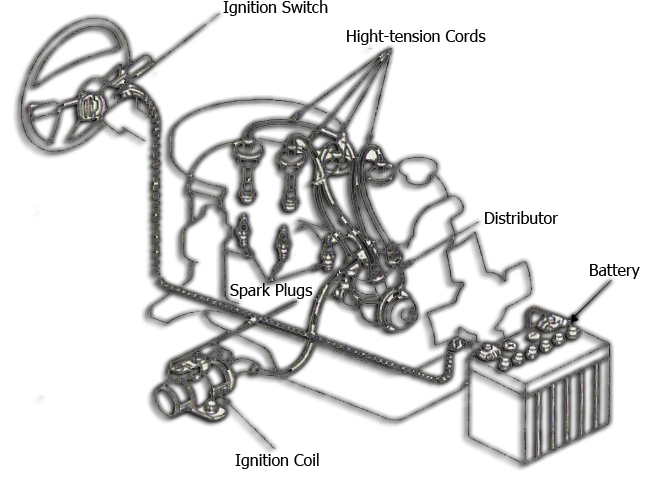
ignition system components are generally as follows: battery, ignition, coils, platinum, condenser, distributor, spark plugs.
Function of the individual components of a conventional ignition are:
- battery serves as a source of low voltage current
- Serves as a key contact breaker and the current from the battery connector to the ignition coil
- Coil serves as a generator of high voltage current of about 15000-20000 volts
- Platinum serves as a circuit breaker and a liaison primary current of the coil to the negative mass
- Condenser serves as an absorber of a spark jumps the gap platinum, and serves to strengthen the primary winding magnetization on platinum after closing.
- Distributor serves as a regulator of the flow of high voltage to each spark plug in accordance with the ignition sequence (Firing Order)
- Spark plug serves to generate a spark in the combustion chamber.
the nature of the ignition system
the ignition of fuel combustion are classified into two types:
a. ignition own
• As a result of compression at high pressures, temperatures reaching 700 º C to 900 º C.
• Fuels that included burning by itself.
• The use of the diesel motor.
b. Electrical ignition system with spark ignition
• At the end of the compression stroke the mixture, the fuel and air burned with an electric spark jumps.
• The use of gasoline motors.
Ignition system on a motorcycle
Ignition system on a motorcycle there are two kinds:
a. Battery ignition system
b. Magnetic ignition system
Description
a. Battery ignition system Ignition is battery ignition system that uses a battery as current source.
1. Basic working principle12V battery voltage is transformed into a high voltage 5kV - 25kV, then flows to the spark plug in turn is regulated by the rotor in order of ignition (firing order)
2. Properties:
• The good ignition at low rpm.
• When the ignition is determined by engine speed and engine load.
• When the ignition can be set using the contact breaker mechanically or electronically.
b. Magnetic ignition system Ignition is battery ignition system that uses a generator as current source.
1. Basic working principle Ignition magnet is a combination of generator and ignition system.
2. The properties
• The source voltage of the generator, so that the motor can live without a battery.
• The good ignition at high speed.
• Round start must be greater than 200rpm.
• Often used in such a small motor bike.
3. Basic transformation of the voltage (the principle of magnetic induction)
a. The magnetic field If the magnetic field moving near the coil, then:
• There is a change of magnetic fields.
• Occur electricity voltage (induced voltage).
b. Transformer If the primary connection transformer is connected to an alternating current is:
• There is a change in electrical current.
• There is a change of magnetic fields.
• There was an induction voltage.
c. Comparison of the voltage Comparison of the voltage proportional to the ratio number winding.
• If the amount of twist a little, then the induced voltage is small.
• If the amount of twist a lot, then the induced voltage is large.
d. Transformation with direct current Transformer will not work with direct current as:
• Flows remained.
• There was no change in the magnetic field.
• No induction.To fix this, should be a switch on the primary connection. If the switch is opened / closed (on / off), then:
• Primary flow falters.
• There is a changing magnetic field.
• There was an induction.
4. The properties of self-induction
• The voltage can exceed the voltage current source, the ignition system voltage ≈ 300 - 400V.
• Induction of self-interest is the cause of the fire on the contact breaker.
• Direction of self-induced voltage is always inhibited the primary current.
Various kinds of ignition systems and how it works:
1. Battery ignition
The principle of formation of electric sparks (spark) igniter battery:
1. When the stop position on the contact and the circuit breaker or platinum (breaker points) is closed, the electric current will flow from the battery to the coil contained within the primary coil, secondary coil, and the soft iron core, resulting in a magnetic field.
2. When the primary current due to the platinum cut open by rotating movement of the peak (cam) then the magnetic field will disappear and the resulting induced current in the secondary coil capable of generating voltages up to ± 5000 - stepping 25.000V causing electrical sparks (spark) on the spark plugs
3. When there is a spark then on each spark gap will also occur, including platinum, to the mounted condenser to absorb the induced current, so it does not occur on the platinum spark
2. Magnetic ignition system
The principle of the formation of an electric spark igniter magnet:
1. When the stop position on the contact and the circuit breaker or platinum (breaker points) is closed, then at anchor along the primary coil or rotating magnet spins, the magnetic field will occur in the coil.2. When the primary current due to the platinum cut open by rotating movement of the peak (cam) then the magnetic field will disappear and the resulting induced current in the secondary coil capable of generating voltages up to ± 5000 - stepping 25.000Volt causing electrical sparks (spark) on the spark plugs.3. When there is a spark then on each spark gap will also occur, including platinum, to the mounted condenser to absorb the induced current, so it does not occur on the platinum spark.
3. CDI Ignition (Magneto Capasitet Discharge Ignition)
The working principle of CDI• The voltage generated by the primary coil power delivered by the diode rectifier and stored in a capacitor.• When generating a voltage pulser coil that flows to the transistor through the diode will open the transistor.• Transistor open, then quickly drain current of the capacitor to the primary coil.• The faster the magnetic field is generated and the high voltage generated in the secondary coil.
ProfitEfficiency ignition / ignition power is greater in comparison with the contact breaker
LossOnly suitable for small motors cylinder volume due to the nature of the dumping capacitor quickly.
a. Ignition CDI - DC
How it works• The current from the battery into trasformer then cut-off by swich circuit to increase the voltage of the battery.• The high voltage of the transformer in unidirectional by the diode, then enter the SCR so that the SCR to be active (on), and also stored in the capacitor.• The current of the capacitor also flows into the primary coil and then to the masses so that the resulting magnetic field at the core of the coil.• When the pick-up through the pulser, pulser voltage issue and into the Ignition Timing Control Circuit to determine the ignition time by sending pulses (current) to the SCR.• Then the SCR gate open so that the mass dumping.• There is a change in the magnetic field induction coil that generates a high voltage in the secondary coil which generates an electric spark jumps the spark plugs.
b. Ignition CDI - AC
How it works• magnet rotates so that the exciter coil (spoil) issued a current AC 100-400 V.• Flow AC converted to DC by the diode current and stored in the capacitor and the primary coil, to the masses so that the resulting magnetic field at the core of the coil.• DC current of the diode also went into the SCR, so that the SCR becomes active.• Then generate a voltage pulser and into the ignition trigger that determines when to send a pulse (current) to the SCR.• SCR Gate is open so that the capacitor dump its cargo into the mass.• There is a change in the magnetic field induction coil that generates a high voltage in the secondary coil which generates an electric spark jumps the spark plug
source: http://sukiyasa.blogspot.com/2008/04/sistem-pengapian.html
http://korekmesin.wordpress.com/2010/12/21/sistem-pengapian-pada-sepeda-motor/


")